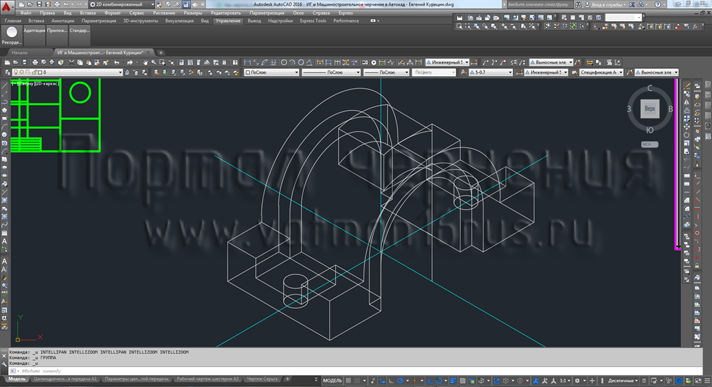
Isometric in AutoCAD
In the previous vidoeuroke we reviewed the implementation of drawings principle isometric in AutoCAD. This video tutorial will fix the material covered by drawing isometrics details. Drawing items we take out of the video on the 3D modeling in AutoCAD Part 1.
The video tutorial is mainly used Polar Tracking reference angles in AutoCAD, which helped to build objects with respect to the axes of perspective. To construct a circle in isometric view used directly in an isometric projection in AutoCAD, because in this mode, the construction of the circle in the plane isometry automatically.
You can use tracing components in isometric view in AutoCAD instead of tracking polar supporting angles - isometric view mode in AutoCAD and ORTHO mode. In this case, made a forced snapping the cursor to the axes of the rectangular isometric view, and a retreat of construction objects distinct from the axes is not possible (with the exception of using object snaps in AutoCAD).
In constructing the detail in isometric view in AutoCAD, you can alternate the two methods, depending on the situation.
Video "How to draw (draw) isometric detail in AutoCAD Part 1" (Russian)


Subscribe
My comments