


Coordinates in AutoCAD
 No comments


Free AutoCAD video tutorials "Two-dimensional design" (full edition) included in the professional video course. Get training from scratch on your own, without leaving your home online! Autocade video course comes from the version of the program 2012 - 2018/2019. Video tutorials are recommended for novice users "dummies", and already working in the program. Lessons are included in the illustrated textbook book. Articles. Video.
Having mastered the AutoCAD 2D video tutorials (two-dimensional design), you can create projects from simple to the most complex. You will learn a lot of useful information necessary for confident work in the program. The training program is based on high-quality, detailed, phased video lessons AutoCAD 2D, where there is nothing superfluous!
Complete this free video course from scratch on your own and consolidate your skills with practical tutorials, because there are exciting AutoCAD 3D Lessons.
{rscomments off}
No comments
Each student before starting the study program asks the question: "Where to download the free version of the program AutoCAD?". Download the demo version of the program is not rational, because license for it is not more than 30 days.
СDownload AutoCAD pirated version of dangerous:

| AutoCAD drawing command | |
| Revision cloud | |
 |
|
| Definition | |
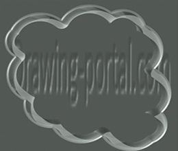
| Revision cloud in AutoCAD is closed polyline consisting of arc segments. | |
| Tool | |
| Tool Revision cloud allows you to build auxiliary correctional clouds in drawing and is used to highlight viewed fragments.. | |
| Command | |
| Cloud | |
| Object | |
| Polyline |
Basically, corrective clouds are used to draw attention to individual fragments of drawing at stage of its verification and review.
The Cloud command is responsible for its creation, which can be called in one of following ways (start creating cloud):

| AutoCAD drawing command | |
| Elliptical Arc | |
 |
|
| Definition | |
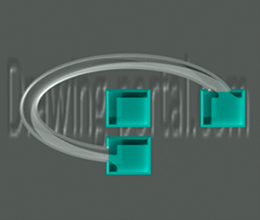
| Elliptical arc in AutoCAD is part of ellipse. | |
| Tool | |
| AutoCAD tool Elliptical Arc an option of Ellipse command that allows you to build elliptical arcs. first two points of an elliptical arc determine location and length of first axis. third point defines distance between center of elliptical arc and end point of second axis. fourth and fifth points define starting and ending angles. | |
| Command | |
| Command Option Ellipse | |
| Object | |
| Ellipse |
The Elliptical Arc tool in AutoCAD is very rarely used and exists in conjunction with Ellipse command, since it is an additional functionality of command.
For creating an elliptical arc in AutoCAD, Arc option of Ellipse command is responsible. Call this option in following ways (start building an elliptical arc):

| AutoCAD drawing command | |
| Ellipse | |
 |
|
| Definition | |
| An ellipse in AutoCAD is geometric figure, which by default is defined by two axes (the major and minor axis of ellipse). Note: program determines which axis is large and which is small, based on their relative length. If you set an equal length of axes of ellipse, you get circle, which is an ellipse object in AutoCAD. |
|
| Tool | |
| Ellipse tool is command that allows you to build ellipses and elliptical arcs. first two points of ellipse determine location and length of first axis. third point defines distance between center of ellipse and end point of second axis. | |
| Command | |
| Ellipse | |
| Object | |
| Ellipse |
In two-dimensional design, Ellipse object in AutoCAD is used quite rarely, but quite often in isometric design. Ellipse team allows you to build circles in axonometry, since it has Izokrug tool in its functionality.
For creation of an ellipse in AutoCAD, command Ellipse/Ellipse is responsible, which can be called up in following ways (start its construction):

| AutoCAD drawing command | |
| Arc | |
 |
|
| Definition | |
| Arc in AutoCAD is primitive object that is part of circle. Semicircle is an arc that represents half circle. |
|
| Tool | |
| Arc tool is command that allows you to build flat Arc objects in combinations of parameters such as center, start and end point, radius, center angle, chord length and direction. | |
| Command | |
| Arc | |
| Object | |
| Arc |
For creation of arc in program, Arc command is responsible, which can be called in one of following ways (start building arc):
The program does not have ability to break circle at point, so many people represent circle in video of two arcs - semicircles. Such technique is used mainly in three-dimensional modeling or in complex curved lines (their conjugations).

| AutoCAD drawing command | |
| Rectangle | |
 |
|
| Definition | |
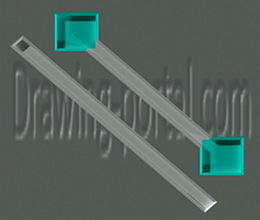
| A rectangle is geometric flat figure - parallelogram, whose opposite sides are equal and all angles are right. long side of rectangle is called length of rectangle, and short side is called width. rectangle in AutoCAD is two-dimensional closed polyline consisting of four line segments. | |
| Tool | |
| Rectangle tool builds rectangular 2D polyline using specified rectangle parameters (length, width, rotation angle) and type of corners (mate, chamfer or straight). | |
| Command | |
| Rectang/Rectangle | |
| Object | |
| Polyline |
You can draw rectangles in AutoCAD using Segment command or Polyline command. However, y are quite often found on drawings, so developers came up with special command Rectangle. In older versions of program, command name is abbreviated: "Straight". In new versions of system, after having worked well with localization (y translated reference book), team began to wear full name - "Rectangle".
By default, creation of rectangles in AutoCAD is based on specifying location of its two diagonally opposite vertices. constructed rectangle is located parallel to axes of current UCS.
You can call Rectangle tool in following ways (start its construction):

| AutoCAD drawing command | |
| Ray | |
 |
|
| Definition | |
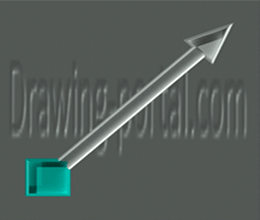
| Ray - straight line (linear object), having beginning (limited on one side), but not having an end. | |
| Tool | |
| Ray tool is cyclic command that allows you to build auxiliary lines (rays) starting at common point and endless in one direction. | |
| Command | |
| Ray | |
| Object | |
| Ray |
Principle of creating ray is very similar to construction of object "Direct". Object AutoCAD "Ray" is also an auxiliary line and is mainly used to construct or objects, and ir markup.
Ray team is responsible for its creation, which can be called in following ways:

| AutoCAD drawing command | |
| Straight line | |
 |
|
| Definition | |
| Straight line is endless line in both directions. | |
| Tool | |
| Tool Straight line is cyclic command that allows you to build auxiliary lines (straight lines) starting at common point and endless in both directions. | |
| Command | |
| Xline | |
| Object | |
| Straight lin | |
| Line drawing commands | |
| Ray, Xline, Line, Polyline |
Old and new versions of program use Direct tool, which allows you to create auxiliary straight lines. In old versions of system, auxiliary lines were used extensively, so almost every drawing began with marking up Liszt (Model) space of future part, and then it was only encircled by segments, arcs and other objects. drawing was edited. In modern versions of system, any drawing can be drawn without using auxiliary straight lines in AutoCAD, because we have such powerful bindings and tracking tools at our disposal.
For creation of auxiliary straight line in AutoCAD, Direct command is responsible, which can be called in following ways:

| AutoCAD drawing command | |
| Multiline | |
 |
|
| Definition | |
| Multiline in AutoCAD is set of parallel lines that are created simultaneously using one command. | |
| Tool | |
| The Multiline tool is cyclic command that allows building parallel segments perceived by program as single object (a multi line has its own properties and editing tools). | |
| Command | |
| MLine | |
| Object | |
| Multiline |
In video tutorial we will learn to build in AutoCAD multiline. Responsible for creation of multiline - team Mline.
In this video tutorial we will consider options of AutoCAD Multiline command:
We will also dwell on creation of multiline style in AutoCAD, which is created using "MSTTIL" command. Let us examine multiline style dialog box and all necessary parameters when creating new multiline style in program.

| AutoCAD drawing command | |
| Spline | |
 |
|
| Definition | |
| Spline in AutoCAD is smooth Bezier curve, which by default passes through specified points or deviates from them within tolerance. AutoCAD spline (complex) is piecewise smooth polynomial NURBS curve (NURBS - Non-Uniform Rational Bezier Spline) - non-uniform rational Bezier spline - Bezier curve, as special case of B-spline, passing near set of control points. | |
| Tool | |
| AutoCAD Spline tool is command that allows you to build smooth curves passing through specified points or near set of defining points, as well as defined vertices in shape and position tolerance. | |
| Command | |
| Spline | |
| Object | |
| Spline |
Существует несколько типов сплайнов, но все они обладают аналогичными свойствами.
The Spline command is responsible for building spline in program. Call which you can (start building spline):

| AutoCAD drawing command | |
| Polyline | |
 |
|
| Definition | |
| Polyline is universal line that consists of segments of both straight and arc segments that are perceived as single object. | |
| Tool | |
| Polyline tool is command that allows you to build 2D polylines representing connected sequence of linear and arc segments (perceived as one object) | |
| Command | |
| Polyline | |
| Object | |
| Polyline |
Objects considered earlier: rectangle, polygon, mark cloud (correctional), ring - all of them consist of polylines. If you select any of these objects and open properties panel in window, “Polyline” will be written in window header, so these objects can be created directly in program using AutoCAD Polyline tool.

| AutoCAD drawing command | |
| Point | |
 |
|
| Definition | |
| A point in AutoCAD is point object, which can have form of both regular point and special character. Often they are also called AutoCAD nodal or anchor points, since binding to them is carried out using Object snapping node, and anchor points, as they are used to clarify/designate coordinates of objects. | |
| Tool | |
| Инструмент Автокад Точка - циклическая команда, позволяющая строить объекты-точки. | |
| Command | |
| Point | |
| Object | |
| Point | |
| System variables | |
| PDMODE и PDSIZE - set appearance of points and their sizes. |
Points in AutoCAD are used quite often and mainly as reference nodes. They are printed as any object and by default system creates special layer for them. Let's not get ahead of ourselves and consider creation, adjustment of points in program.
The Point command is responsible for its creation, which can be called in one of following ways (start creating point):

| AutoCAD drawing command | |
| Donut | |
 |
|
| Definition | |
| Donut in AutoCAD is an object representing two concentric circles, internally space between which is filled with current color or, in other words, polyline in AutoCAD of given width. | |
| Tool | |
| Tool AutoCAD Donut cyclic team that build circle with fill or wide Donut. | |
| Command | |
| Donut | |
| Object | |
| Polyline |
For construction of Donut in AutoCAD, command "Donut" is responsible, which can be called in one of following ways (start creating ring):
