Rotate command in AutoCAD
During rotation of objects (line, table, text, viewport, etc.) in AutoCAD responds Rotate command.
Rotate command in addition to the two-dimensional design in AutoCAD is also used in three-dimensional modeling.
Example drawing turning on descriptive geometry in AutoCAD.
Call the Rotate command in AutoCAD, use one of the following methods:
- Modify from the menu line - Rotate line;
- Home tab of the ribbon tools - in the Modify group - Rotate button;
- on the Modify toolbar - Rotate button;
- or to register the name of the command in the Rotate command line.
How to rotate an object in AutoCAD at a certain angle
Call the command Rotate. At the command prompt, you are prompted:
Select objects:
Before Rotate command call, you can pre-select the object or group of objects to rotate at a predetermined angle, as AutoCAD rotation operation may be performed in both the pre-mode or in deferred mode selection. Select the rectangle and press Enter. AutoCAD prompts you:
Specify base point:
Now you need to specify the base point, ie, the point about which the object will be the turn (rectangle) in AutoCAD. We give top right corner of the rectangle using the Endpoint object snap (Endpoint). Once you specify a base point, you will see a preview of the rotated object, which will rotate following a change-cursor crosshair position. Default will be dashed yellow line that will follow from the base point to the rotation cursor, crosshair (visual indication angle in AutoCAD). Rotation icon appears next to the crosshair. AutoCAD prompts you:
Specify rotation angle or [Copy/Reference] <0>:
The angle of rotation of the object can be set using:
- mouse - click (using the polar tracking, object snap);
- enter the angle value in the command line;
- set the coordinates of the point.
Enter the angle value in the command line of 45 degrees, and press Enter. As soon as we give the rotation angle, AutoCAD will generate a rectangle rotate counter-clockwise by 45 degrees, and Rotate command closes down.
In AutoCAD there is a rule of rotation by default objects. If you want to change it, I suggest to look into the section "Individual settings AutoCAD" or article "How to create a drawing in AutoCAD."
Accordingly, if you want to turn AutoCAD object in a clockwise direction, then enter a negative angle in the command line.
Creating rotated copies of the object in AutoCAD
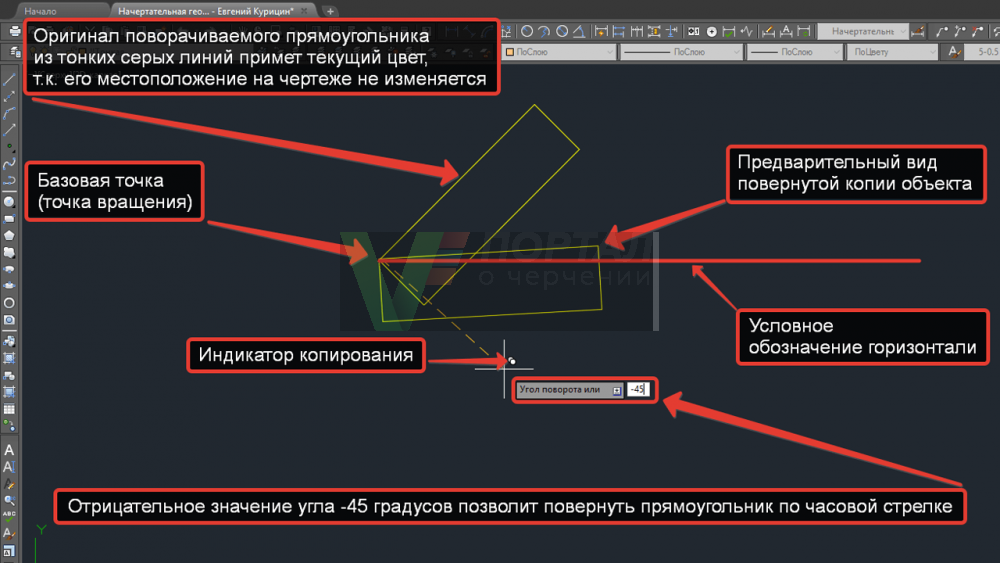
Functional Rotate commands in AutoCAD allows to make rotated copies of objects around a base point of rotation. Responsible for the feature the option Copy Rotate command.
Choose a rectangle rotated 45 degrees to the horizontal. Call the command Rotate. At the command prompt, you are prompted:
Specify base point:
We indicate the upper left corner of the rectangle using the Endpoint object snap. AutoCAD prompts you:
Specify rotation angle or [Copy/Reference] <45>:
We choose the Copy option. Please note that the original is rotated rectangle of thin gray lines will take the current color, as its location in the figure does not change. AutoCAD will repeat the request:
Specify rotation angle or [Copy/Reference] <45>:
Enter a negative angle -45 °, to rotate the object in AutoCAD clockwise, and press Enter. As soon as we give the value of the steering angle, AutoCAD will make a copy of a rotated object, and Rotate command closes down.
Rotating objects in AutoCAD using reference angle
Reference option allows you to set the so-called reference angle in front of the object rotation. By default, the reference angle in AutoCAD is 0. Reference option in AutoCAD is used in almost all the commands that are associated with the rotation of objects, or the rotation of 3D-bodies.
Consider the use of a reference angle in AutoCAD (developers so namudrili him that the jungle will not climb).
A common way to rotate an object in AutoCAD to an unknown angle with reference to this angle (through the object point coordinates).
Select the rectangle placed at an angle of 45 ° to the horizontal.
Call the Rotate command in AutoCAD. Specify a base point about which the object will rotate. This point will be the lower left corner of the rectangle.
Select the Reference option. AutoCAD prompts you:
Specify the reference angle <0>:
Опорный угол в Автокад по умолчанию равен 0. Опорный угол отсчитывается от горизонтальной линии направленной в право.
Let us support the angle of two points in the drawing using the Endpoint object snap. As the points will play the final point of the bottom side of the rectangle. Once specify a reference angle, the bottom side of the rectangle sketch as it snaps to the cursor crosshair will turn followed by a change of its position.
Arrange the lower side of the rectangle at an angle of 90 degrees to the horizontal. To do this, using the polar tracking with mouse clicks new angle of 90 °.
Video "Copy and rotate objects in AutoCAD" (Russian)


Subscribe
My comments